Industrial electricians frequently encounter a frustrating problem: PLC control cabinets continue showing leakage currents even after careful installation. The culprit often isn’t the PLC modules themselves but inadequate ferrule terminal connections. When wire ends lack proper ferrule termination, loose strands create micro-arcing, oxidation, and gradual connection degradation that manifests as leakage current. Understanding PLC cabinet ferrule terminal safety principles can eliminate 80% of these recurring issues. This comprehensive troubleshooting guide reveals three critical factors that separate reliable industrial control wiring from problematic installations, helping you prevent costly downtime and safety hazards in automation systems.
Understanding PLC Cabinet Leakage Problems
Leakage current in PLC systems typically ranges from microamperes to several milliamperes, yet even minimal amounts can trigger residual current devices (RCDs) or cause erratic behavior in sensitive control circuits. Unlike traditional power distribution, PLC cabinets combine low-voltage DC signals with 24V control circuits and 230V/400V power supplies, making them particularly vulnerable to grounding issues and stray currents.
Common Symptoms of Poor Ferrule Terminal Connections
Industrial maintenance teams often misdiagnose PLC cabinet leakage as module failures when the actual problem lies in terminal connections. Warning signs include:
Intermittent RCD tripping without obvious load changes
Unexplained I/O module communication errors
Heat discoloration around terminal blocks
Occasional system resets or watchdog timer faults
Ground fault indicators activating during normal operation
These symptoms typically worsen in high-humidity environments or after temperature cycling, as poor connections expand and contract differently than solid metal contacts.
Why Ferrule Terminals Matter in PLC Systems
Ferrule terminals solve a fundamental problem in control panel wiring: preventing multi-strand wire separation. When flexible wires connect directly to screw terminals without ferrules, individual copper strands can escape during vibration, create high-resistance joints that generate heat, short to adjacent terminals, and oxidize over time. The IEC 60947 standard specifically addresses terminal connection quality in low-voltage switchgear, emphasizing that ferrule terminals provide significantly more reliable connections than bare wire ends in industrial environments.
Key #1 – Correct Ferrule Size Selection
The most common mistake causing PLC cabinet ferrule terminal safety issues is using incorrect ferrule sizes. Proper size matching ensures gas-tight connections that resist oxidation and maintain low contact resistance throughout the equipment’s service life.
Matching Wire Gauge to Ferrule Dimensions
PLC control wiring typically uses conductors from 0.5mm² to 6mm² depending on circuit function. Each wire gauge requires a precisely matched ferrule size to ensure proper crimping and terminal insertion.
Critical sizing requirements for PLC applications:
0.5mm² to 0.75mm² – I/O module connections, sensor wiring, communication lines (gray ferrules per DIN 46228)
1.0mm² to 1.5mm² – Standard 24V DC power distribution, relay coil connections (blue ferrules)
2.5mm² – Main 24V power feeds, critical ground connections (red ferrules)
4mm² to 6mm² – AC power input terminals, high-current DC circuits (black ferrules)
Using oversized ferrules leaves gaps around the conductor, allowing wire movement inside the ferrule barrel. This creates intermittent high-resistance contacts that generate heat and eventually fail. Undersized ferrules either crush the conductor—reducing ampacity and creating weak points—or don’t fully insert into terminal blocks, leaving exposed copper that can short to adjacent circuits.
Color-Coding Standards for Industrial Safety
Industrial ferrules follow standardized color coding that prevents cross-connection errors. While the metal barrel performs the electrical function, the insulated collar provides visual identification and insulation safety. Professional installations use color-coding to distinguish circuit types:
Signal and communication wiring (0.5-0.75mm²) uses gray insulation
Control circuits and relay wiring (1.0-1.5mm²) uses blue insulation
Power distribution within cabinets (2.5mm²) uses red insulation
Main power feeds (4-6mm²) use black insulation
This system immediately identifies wiring errors during commissioning and maintenance, reducing the risk of connecting power circuits to sensitive signal inputs—a common cause of equipment damage in PLC systems.
Key #2 – Proper Crimping Technique and Depth
Even correctly sized ferrules fail if not properly crimped. PLC cabinet ferrule terminal safety depends on achieving consistent, high-quality crimps that maintain full contact pressure throughout years of thermal cycling and vibration.
Achieving the Perfect Crimp Profile
Unlike insulated terminals that crimp onto both conductor and insulation, ferrule terminals require precise compression of only the metal barrel. Professional ferrule crimping tools create a hexagonal or square profile that:
Compresses all wire strands uniformly – Each conductor strand must be mechanically locked into the ferrule with equal pressure, preventing individual strand movement that creates micro-gaps and increases resistance.
Avoids over-compression – Excessive crimping force breaks individual copper strands or cracks the ferrule barrel, creating weak points that fail under mechanical stress or thermal cycling.
Creates gas-tight connections – Proper compression eliminates air gaps between strands, preventing oxidation that increases contact resistance over time.
According to IEC 60352-2 standards for crimp connections, properly crimped ferrules achieve a minimum pull-out force of 50N for 1.5mm² conductors. Under-crimped connections can be removed by hand, while over-crimped connections show visible conductor damage or ferrule deformation.
Inspection Standards for Quality Control
Professional PLC installation requires 100% visual inspection of crimped ferrules before insertion into terminal blocks. Quality control personnel check for:
Crimp symmetry – The hexagonal profile must be centered on the ferrule barrel without rotation or off-center deformation
No conductor damage – Wire strands shouldn’t protrude from either end or show breakage through the ferrule sides
Proper insertion depth – Conductors must fill the ferrule completely with no gaps between wire end and ferrule bottom
Insulation clearance – Maintain 1-2mm gap between crimp point and wire insulation to prevent insulation damage
High-reliability installations include pull-testing of random samples at 80N force to verify crimp integrity. Any ferrule that fails pull-testing indicates improper tool calibration or technique errors requiring immediate correction.
Key #3 – Terminal Block Insertion Best Practices
Perfect ferrule crimps become unreliable if not properly inserted into terminal blocks. PLC cabinet ferrule terminal safety requires attention to insertion depth, tightening torque, and connection verification.
Spring-Cage vs Screw-Clamp Terminals
Modern PLC cabinets use two primary terminal types, each requiring different insertion techniques for reliable connections:
These push-in terminals use spring pressure to maintain contact force. Insert the ferrule until it bottoms out in the terminal chamber—the release mechanism should audibly click. The ferrule collar must be flush with the terminal entry point. Typical insertion depth is 10-12mm for standard terminals. Spring-cage terminals maintain consistent contact pressure despite thermal cycling but require fully inserted ferrules to engage the spring properly.
Screw-Clamp Terminals (traditional DIN rail blocks):
These conventional terminals rely on screw pressure to secure connections. The ferrule must extend 8-10mm into the terminal chamber before tightening. Use a calibrated torque screwdriver set to manufacturer specifications (typically 0.5-0.8 Nm for small terminals, 1.2-1.5 Nm for larger power terminals). After tightening, verify no wire strands are visible outside the ferrule—this indicates either incorrect ferrule size or insufficient insertion depth.
Grounding Connection Requirements
Ground fault leakage in PLC systems often originates from inadequate PE (protective earth) connections. Critical PLC cabinet ferrule terminal safety practices for grounding include:
Use insulated ferrules for all PE connections – Prevents accidental shorts during maintenance when technicians work on live cabinets
Dedicated ground bus bar – Never daisy-chain ground connections through terminal blocks; each ground wire should connect independently to a central grounding point
Minimum 2.5mm² ground conductors – Even low-power I/O modules require substantial ground wires to safely carry fault currents
Star-point grounding topology – All cable shields and equipment grounds must return to a single cabinet grounding point to prevent ground loops
The central grounding point should connect to the cabinet frame via braided copper strap or heavy copper bar—never through painted surfaces or small screws that create high-resistance paths.
Common Ferrule Crimping Errors in PLC Cabinets
Despite following general guidelines, several specific errors repeatedly cause PLC cabinet leakage issues in industrial installations.
Using Wrong Crimping Tools
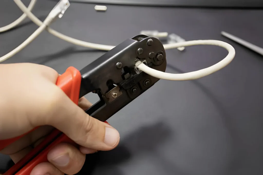
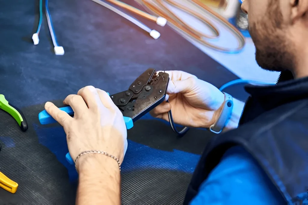
Hand crimpers without ratchet mechanisms allow incomplete crimps that appear correct visually but fail under vibration or thermal stress. Quality PLC installation requires:
Ratchet crimping tools – These ensure complete crimp cycles by preventing premature release; the tool locks until full compression is achieved
Correct die size – Each ferrule size requires a specific die cavity; using adjustable crimpers with close-enough settings produces inconsistent results
Calibrated tools – Professional installations verify crimp force periodically using certified pull-testing equipment
Low-cost crimpers often use rounded dies instead of proper hexagonal profiles, creating four-point contact instead of six-point contact. This reduces contact area by approximately 30% and increases connection resistance proportionally.
Reusing Crimped Ferrules
When reworking PLC panel wiring during commissioning or troubleshooting, technicians sometimes attempt to remove and reuse ferrules to save time. This practice severely compromises PLC cabinet ferrule terminal safety because a single crimp cycle permanently deforms both the ferrule barrel and wire strands.
Reused ferrules exhibit:
40-60% reduction in pull-out force compared to fresh crimps
Increased contact resistance measurable with milliohm meters (often doubling from 2-3mΩ to 5-8mΩ)
Gaps between deformed ferrule walls and conductor strands allowing moisture ingress and accelerated oxidation
Visible cracks in ferrule barrels that create stress concentration points leading to mechanical failure
Professional practice requires cutting off old ferrules and crimping fresh terminals during any circuit rework, regardless of how recently the original crimp was performed.
Troubleshooting Existing Leakage Issues
When facing persistent leakage current in operating PLC cabinets, systematic diagnosis identifies the problematic connections without unnecessary equipment replacement.
Systematic Diagnosis Steps
Follow this sequence to isolate leakage sources in PLC installations:
Measure total leakage current – Use a clamp meter on the main ground conductor to quantify total leakage (normal installations show <5mA)
Isolate by circuit – Disconnect I/O modules and power supplies sequentially while monitoring leakage current to identify the problematic section
Visual inspection of ferrule terminals – Look for heat discoloration (brown or black marks), loose ferrules (wiggle test), or visible corrosion on terminal blocks
Contact resistance measurement – Use a precision milliohm meter to check each terminal connection (should be <5mΩ; readings above 10mΩ indicate problems)
Check for moisture contamination – Cabinet condensation or spray wash residue creates leakage paths through contaminated terminal surfaces
Thermal imaging often reveals poor ferrule connections as hot spots running 10-20°C above ambient temperature even under normal operating current. This technique quickly identifies problematic connections in densely wired cabinets without disconnecting circuits.
Preventive Maintenance Schedule
Recommended inspection intervals for PLC cabinet ferrule terminal connections:
Initial commissioning – 100% inspection with pull-testing of sample connections
First 3 months – Re-tighten all screw terminals as thermal cycling causes relaxation
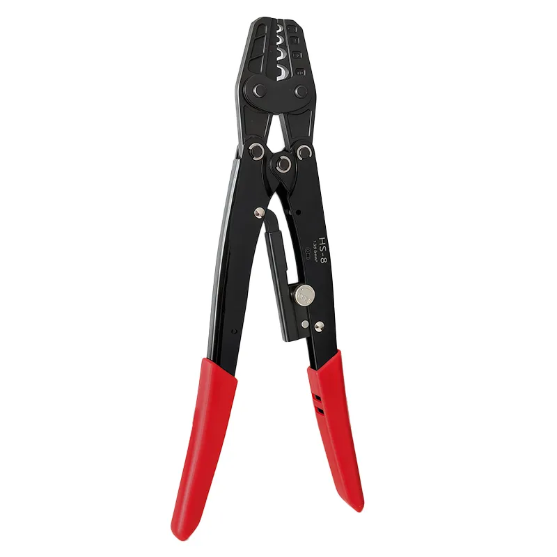
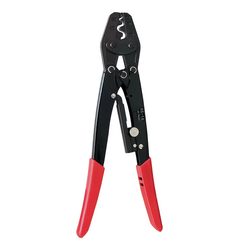
Why Upgrade to a Ratcheting Mechanism? If you’re still using traditional crimping tools, switching to a ratchet wire crimper like the JiaPaiMi model brings real benefits. The key advantage lies in its full-cycle crimping tool design, which includes a controlled release system. This means the tool won’t let go until the complete crimp cycle is […]
If you want to join cables and connectors safely, you need to understand crimping first. Crimping joins connectors and cables by compressing metal parts together to create a secure, long-lasting electrical bond. In this guide, you will learn what crimping is and which type of crimping tools you need to get your job done. What […]
We use cookies to enhance your browsing experience, serve personalised ads or content, and analyse our traffic. By clicking "Accept All", you consent to our use of cookies.